
Assembly and installation manual (PDF)
Pictures of the board in various stages of assembly
Schematic as PDF
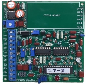
Note: I've temporarily stopped building these kits, but I wanted to leave everything here for the documentation. If you've already bought one and need assistance or need to have it repaired, send me an email at stevedold1960 followed by the "at" symbol, then gmail, followed by dot com.This is an FM audio squelch board that connects to an FM receiver's discriminator/detector and provides all of the audio and logic signals needed to connect to a repeater controller. Space on the board is provided to install an optional CTCSS (PL) decoder. It uses a simple low-power microcontroller to measure the noise level from the discriminator and gives a short or long squelch tail (noise burst) based on the signal quieting level. It provides COS, filtered repeat audio, speaker audio and optional CTCSS decoding using your own board (such as a Comm Spec TS-32). Right now the board works best on wideband radios (+/- 5 KHz deviation, 16 KHz modulation bandwidth) but narrowband radio tests are under way and I be updating the description to reflect this."Why do I need this board?" You might not. If your receiver already provides an audio source that you are happy with (such as the high-side of the volume pot or a pin on a rear connector), and all you need is COS, then there are other options that might fit your needs better. For instance, Masters Communications (http://www.masterscommunications.com/) provides a couple of different boards that use the Motorola Micor squelch IC to provide a COS to an external repeater controller. The Micor chip is as good as it gets if you want a super-short "click" squelch tail and good overall performance. One of his boards even has on-board CTCSS decoding. Link-Comm also makes (or used to make) the RLC-MOT, a small board that also uses the Micor chip, and provides repeat audio, but does not provide speaker audio and doesn't filter out the CTCSS. It's small enough to install in many radios, however. NHRC also makes a similar microprocessor-based board (the NHRC-Squelch) that provides a simple COS signal. All of these boards can give COS to a repeater controller, and that might be all you need. But if you want a board that takes discriminator audio and provides speaker audio, CTCSS-filtered and de-emphasized repeat audio, active high or low COS and a place to mount a CTCSS board, and can live with a 4" x 4" board and don't mind spending a couple of hours building it, then this might be the board for you. The short squelch tail isn't quite as fast as the Micor squelch, but at less than 20 milliseconds, it's not too bad. The board has some interesting options that are configurable with on-board jumpers. One prevents the board from un-squelching if a certain terminal-block connection goes low, this would typically be used to sense a PTT line on a remote base to keep the squelch board from thinking there is a full-quieting signal (and giving COS output) when the remote base radio receiver is muted during transmit. It could also be used as a simple inhibit line for the receiver. Two more configurable options are available if a CTCSS board is installed. One puts the board into carrier squelch for one minute after decoding a valid CTCSS. This is handy for a series of links where you don't want the decode time of CTCSS decoders to "add up" causing missed words at the beginnings of transmissions. The other option puts the board into carrier squelch for one minute after the PTT sense line goes from low to high. This is great for a CTCSS-protected remote base, so that you can momentarily key the transmitter to see if the channel is in use before making a call.
"Do I need to do any programming or know how to write code?"
Features:
|
| The squelch tail length varies depending on the amount of
receiver noise
quieting. The length is about 15-20 milliseconds with a signal that is
nearly full quieting and about 150 milliseconds with a noisy signal.
There is also about 3 dB of hysteresis, meaning a signal that just
opens the squelch must drop by about 3 dB in strength for the squelch
to close. This allows the squelch to stay open on signals that are
"picket fencing" rapidly. The method used for gating the audio
ensures that no "pops" due to DC voltage changes, capacitor
charging/discharging etc. occur when squelching or unsquelching, so
the squelch tail is fairly quiet, being purely receiver noise. Space
is provided on the board to mount a CTCSS decoder such as a Comm-Spec
TS-32 or TS-64, or even a DCS (digital PL) decoder. All of the
necessary connections to the CTCSS board
are provided as solder pads so that all of the interfacing to the
outside (repeater controller, etc.) can be done using the 12-position
terminal strip on the squelch board.
Specifications:
Price for a complete kit is $57 which includes USPS Priority Mail U.S. shipping if you are in the U.S. If you are outside the U.S. please contact me about shipping costs. I can take a check or Paypal. Please call or email me for the paypal payment address, it's different than the email address below.
Contact info:
Assembly and installation manual (PDF)
|